


MARKETS


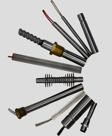
Cartridge & Immersion Heaters
PRODUCTS
- Backer Hotwatt
- / Our Products
- / Cartridge Heaters
- / Superwatt High Watt Cartridge Heaters High Watt Density
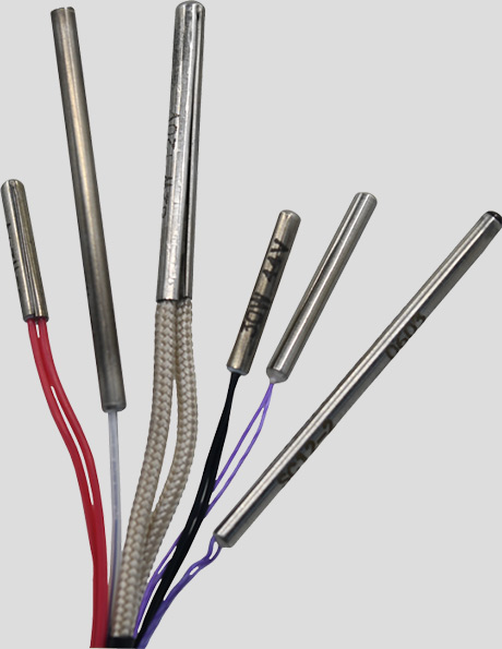
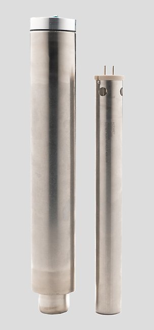
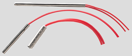
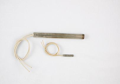
SUPERWATT® - High Watt Density Heaters


Availability: In Stock
Description
U.L. Recognized – E56973
C.S.A. Certified – 016386-0-000
Cartridge Heaters: Superwatt High Watt Density In-Stock
Application
Dies, Heat Sealing, Hot Melt Adhesive, Plastic Molding, Platens, Shoe Machinery.
Features
- Elements are designed for maximum: Watt density, temperature, heat transfer, and heater life.
- The useful life of a cartridge heating element is determined by how quickly the heat generated in the resistance wire can be dissipated to the outside sheath. With low and moderate watt density elements, such as Backer Hotwatt’s standard line, the conventional method of inserting helical coils in formed ceramics is an entirely satisfactory method of construction because the wire temperature relative to sheath temperature even though considerably higher, is still well within safe long-life operating temperatures.
- The Superwatt cartridge heater accelerates the transfer of heat from the resistance wire to the sheath. This is accomplished by relocating the wire so that it is closer to the sheath; and swaging the outside diameter of the heater, thereby compressing the magnesium oxide filler so that it becomes an improved conductor of heat from the wire while maintaining its dielectric properties. (See diagram below). By improving the heat transfer rate, it is possible to manufacture elements of higher densities because the differential between the wire temperature and the sheath temperature has been minimized.
- Long, trouble free service.
- Made in U.S.A
Construction
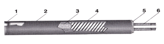
- Heliarc welded end seal.
- Series 300 stainless steel sheath of precision dimensions and tolerances for intimate, stable, non-oxidizing contact with cavities machined for them.
- Pure magnesium oxide compressed to an optimum density for best heat transfer and electrical insulation at elevated temperatures.
- Element wire situated in close proximity to outside surface for maximum heat transfer and minimum internal temperature while preserving good dielectric qualities.
- Ceramic cap.
- Fiberglass insulated leads.
Lengths between or longer than those listed may be ordered.
Diameter: 1/8″ (.124/.120) | |||
Maximum Amperage: 3.5 Not UL/CSA |
Sheath Length | Cat.No. | Min. Watts | Max. Volts |
|---|---|---|---|
1″ | HS12-1 | CONSULT FACTORY | |
1 1/2″ | HS12-1.5 | CONSULT FACTORY | |
2″ | HS12-2 | CONSULT FACTORY | |
2 1/2″ | HS12-2.5 | 50 | 120 |
3″ | HS12-3 | 60 | 120 |
3 1/2″ | HS12-3.5 | 70 | 120 |
4″ | HS12-4 | 80 | 120 |
Diameter: 1/4″ (.249/.245) | 3/8″ (.374/370) | 1/2″ (.499/495) | |||||||
Maximum Amperage: 4 | 6 | 10 | |||||||
Sheath Length | Cat.No. | Min. Watts | Max. Volts | Cat.No. | Min. Watts | Max. Volts | Cat.No. | Min. Watts | Max. Volts |
|---|---|---|---|---|---|---|---|---|---|
1″ | HS25-1 | 70 | 120 | HS37-1 | 70 | 120 | |||
1 1/2″ | HS25-1.5 | 70 | 120 | HS37-1.5 | 80 | 120 | HS50-1.5 | 110 | 240 |
2″ | HS25-2 | 100 | 120 | HS37-2 | 120 | 240 | HS50-2 | 160 | 240 |
2 1/2″ | HS25-2.5 | 130 | 120 | HS37-2.5 | 160 | 240 | HS50-2.5 | 210 | 240 |
3″ | HS25-3 | 150 | 240 | HS37-3 | 200 | 240 | HS50-3 | 270 | 240 |
3 1/2″ | HS25-3.5 | 180 | 240 | HS37-3.5 | 240 | 240 | HS50-3.5 | 330 | 240 |
4″ | HS25-4 | 210 | 240 | HS37-4 | 280 | 240 | HS50-4 | 380 | 240 |
4 1/2″ | HS25-4.5 | 240 | 240 | HS37-4.5 | 320 | 240 | HS50-4.5 | 430 | 240 |
5″ | HS25-5 | 260 | 240 | HS37-5 | 360 | 240 | HS50-5 | 490 | 240 |
5 1/2″ | HS25-5.5 | 290 | 240 | HS37-5.5 | 400 | 240 | HS50-5.5 | 550 | 240 |
6″ | HS25-6 | 320 | 240 | HS37-6 | 440 | 240 | HS50-6 | 600 | 240 |
6 1/2″ | HS25-6.5 | 350 | 240 | HS37-6.5 | 480 | 240 | HS50-6.5 | 650 | 240 |
7″ | HS25-7 | 380 | 240 | HS37-7 | 520 | 240 | HS50-7 | 700 | 240 |
7 1/2″ | HS25-7.5 | 410 | 240 | HS37-7.5 | 560 | 240 | HS50-7.5 | 750 | 240 |
8″ | HS25-8 | 440 | 240 | HS37-8 | 600 | 240 | HS50-8 | 800 | 240 |
8 1/2″ | HS25-8.5 | 470 | 240 | HS37-8.5 | 640 | 240 | HS50-8.5 | 850 | 240 |
9″ | HS25-9 | 500 | 240 | HS37-9 | 680 | 240 | HS50-9 | 900 | 240 |
9 1/2″ | HS25-9.5 | 530 | 240 | HS37-9.5 | 720 | 240 | HS50-9.5 | 950 | 240 |
10″ | HS25-10 | 560 | 240 | HS37-10 | 760 | 240 | HS50-10 | 1000 | 240 |
10 1/2″ | HS25-10.5 | 590 | 240 | HS37-10.5 | 800 | 240 | HS50-10.5 | 1050 | 240 |
11″ | HS25-11 | 620 | 240 | HS37-11 | 840 | 240 | HS50-11 | 1100 | 240 |
11 1/2″ | HS25-11.5 | 650 | 240 | HS37-11.5 | 880 | 240 | HS50-11.5 | 1150 | 240 |
12″ | HS25-12 | 680 | 240 | HS37-12 | 920 | 240 | HS50-12 | 1200 | 240 |
Red catalog number denotes stock item. See stock section for specific ratings.
Diameter: 5/8″ (.624/.620) | 3/4″ (.749/.745) | 1″ (999/.993) | |||||||
Maximum Amperage: 20 | 28 | 30 | |||||||
Sheath Length | Cat.No. | Min. Watts | Max. Volts | Cat.No. | Min. Watts | Max. Volts | Cat.No. | Min. Watts | Max. Volts |
|---|---|---|---|---|---|---|---|---|---|
1 1/2″ | HS62-1.5 | 130 | 240 | ||||||
2″ | HS62-2 | 200 | 240 | ||||||
2 1/2″ | HS62-2.5 | 270 | 240 | HS75-2.5 | 330 | 240 | HS1.0-3 | 475 | 240 |
3″ | HS62-3 | 340 | 240 | HS75-3 | 410 | 240 | HS1.0-3 | 475 | 240 |
3 1/2″ | HS62-3.5 | 410 | 240 | HS75-3.5 | 495 | 240 | HS1.0-3.5 | 570 | 240 |
4″ | HS62-4 | 480 | 240 | HS75-4 | 575 | 240 | HS1.0-4 | 665 | 240 |
4 1/2″ | HS62-4.5 | 550 | 240 | HS75-4.5 | 660 | 240 | HS1.0-4.5 | 760 | 240 |
5″ | HS62-5 | 620 | 240 | HS75-5 | 740 | 240 | HS1.0-5 | 855 | 240 |
5 1/2″ | HS62-5.5 | 690 | 240 | HS75-5.5 | 825 | 240 | HS1.0-5.5 | 950 | 240 |
6″ | HS62-6 | 760 | 240 | HS75-6 | 910 | 240 | HS1.0-6 | 1045 | 240 |
6 1/2″ | HS62-6.5 | 830 | 240 | HS75-6.5 | 980 | 240 | HS1.0-6.5 | 1140 | 240 |
7″ | HS62-7 | 900 | 240 | HS75-7 | 1075 | 240 | HS1.0-7 | 1235 | 240 |
7 1/2″ | HS62-7.5 | 970 | 240 | HS75-7.5 | 1150 | 240 | HS1.0-7.5 | 1330 | 240 |
8″ | HS62-8 | 1040 | 240 | HS75-8 | 1240 | 240 | HS1.0-8 | 1425 | 240 |
8 1/2″ | HS62-8.5 | 1110 | 240 | HS75-8.5 | 1325 | 240 | HS1.0-8.5 | 1520 | 240 |
9″ | HS62-9 | 1180 | 240 | HS75-9 | 1400 | 240 | HS1.0-9 | 1615 | 240 |
9 1/2″ | HS62-9.5 | 1250 | 240 | HS75-9.5 | 1475 | 240 | HS1.0-9.5 | 1710 | 240 |
10″ | HS62-10 | 1320 | 240 | HS75-10 | 1560 | 240 | HS1.0-10 | 1805 | 240 |
10 1/2″ | HS62-10.5 | 1390 | 240 | HS75-10.5 | 1645 | 240 | HS1.0-10.5 | 1900 | 240 |
11″ | HS62-11 | 1460 | 240 | HS75-11 | 1730 | 240 | HS1.0-11 | 1995 | 240 |
11 1/2″ | HS62-11.5 | 1530 | 240 | HS75-11.5 | 1820 | 240 | HS1.0-11.5 | 2090 | 240 |
12″ | HS62-12 | 1600 | 240 | HS75-12 | 1890 | 240 | HS1.0-12 | 2185 | 240 |
14″ | HS62-14 | 1740 | 240 | HS75-14 | 2050 | 240 | HS1.0-14 | 2545 | 240 |
16″ | HS62-16 | 1880 | 240 | HS75-16 | 2210 | 240 | HS1.0-16 | 2920 | 240 |
18″ | HS62-18 | 2020 | 240 | HS75-18 | 2370 | 240 | HS1.0-18 | 3300 | 240 |
20″ | HS62-20 | 2090 | 240 | HS75-20 | 2450 | 240 | HS1.0-20 | 3675 | 240 |
Red catalog number denotes stock item. See stock section for specific ratings.
Obtaining maximum heat transfer and long life
Fit
High watt density heaters require careful fit to insure optimum performance and long life. Backer Hotwatt recommends that installation holes not be drilled and reamed over .002 larger than the nominal hole size required. The heaters are sized so that they never exceed .005 less than the nominal diameter and always at least .001 under the nominal diameter for a slide fit. This close fits insure rapid heat transfer from the heater and also help keep the unit as cool as possible, which contributes to long life.
Cycling
Rapid cycling of heaters from very low to very high temperatures shortens their life considerably. It is recommended therefore, that care be taken to compute the correct wattage for any given installation. Optimum wattage should result in a 50/50 off/on cycle. For very high temperature operation (over 750°F), off/on control might well be replaced by input voltage regulation through variable transformers or silicon rectifiers so that great temperature fluctuations in the heater wire are minimized. Review our article on extending cartridge heater life.
Location of temperature control point
When thermostats are used, the sensing element ought not to be placed further than 1/2″ away from the heater wherever possible. Location further away could conceivably cause the unit to run too hot and thereby shorten life.
For more tips on extending heater life, review our Cartridge Heater Frequently aske questions and article on "How to Extend Heater Life"
Wattage
Minimum wattage is based on 60 watts per square inch. Units with lower watt densities may be manufactured for special conditions such as high temperature or vibration. Minimum wattage available can be determined using the following formula and the values in Table 1:
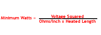
Table 1: Maximum allowable Ohms per inch by diameter
Superwatt Diameter | Maximum Ohms per Inch of Heater Length |
|---|---|
1/8″ | 500 |
1/4″ | 600 |
3/8″ | 800 |
1/2″ | 600 |
5/8″ | 500 |
3/4″ | 400 |
1″ | 300 |
Voltage
Standard voltage is either 120V or 240V. Other voltages are available.
Termination
All units up to 1″ diameter, within published amperage limits, are manufactured with 6″ (type SF1) leads. 1″ diameter units are manufactured with 6″ (type SF2). Longer length leads are available. Stock units supplied with 12″ leads.
Graph A: Maximum watts/sq.in. with various increasing temperatures and hole tolerances.
Hole size over nominal fractional size
The watt densities are based on a unit installed in mild steel. Different materials affect the above values
i.e. the lower the thermal conductivity of the material, the lower the maximum allowable watts per square inch.
Formula for determination of allowable element wattage:
Element Wattage: 3.142 x Diameter x Heated Length x
Maximum watts/square inch from Graph A.
Formula for determination of watts/sq.in:
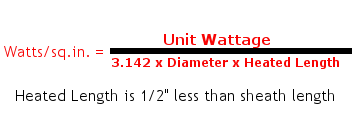
Tolerances
Wattage tolerances is +5% -10% at rated voltage. Length tolerances are ± 2% with a ± 1/16″ minimum. Length tolerances apply to element sheath length.
Camber tolerances for units up to 12″ long is .005″ per six inch length. For units over 12″ long,
tolerance is .020″ per foot of length. This value varies as the square of the length in feet.(i.e. – A 36″ unit has a camber tolerance of .020″ x (3)² = .180″). Normally camber does not present a problem since the unit will flex enough to fit into a straight, close fit hole.
How To Order
After determining the wattage required and the line voltage available: determine the physical space available for heaters and the number of heaters required.
Review Stock list for In-Stock Items.
Review Special Features.
Specify: Catalog number, wattage, voltage, lead type, and special features if required.
Example: HS37-4.25/375W/120V/SF1-18/SF26.