


MARKETS

PRODUCTS
- Backer Hotwatt
- / Our Products
- / Tubular and Finned Tubular
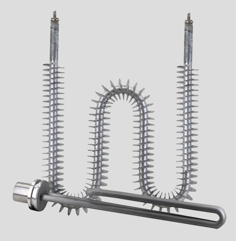
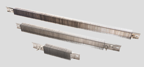
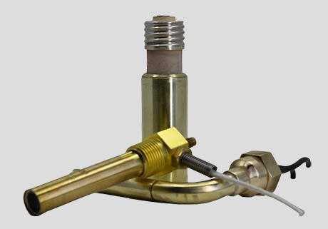
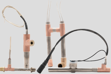
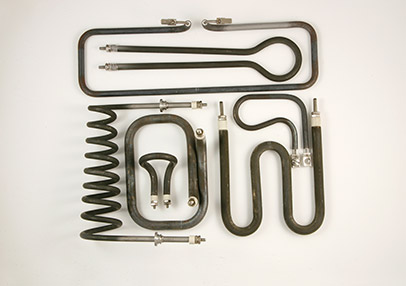
TUBULAR & FINNED TUBULAR Heaters
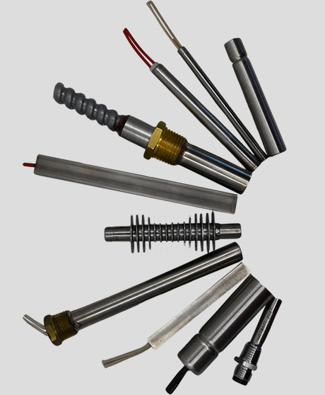
Tubular Heaters & Finned Tubular Heaters are used in multiple applications like cylinders, dies, drums, holding tanks, injections and blow molding machines, and Plastic Extruders as well as many other applications.


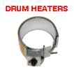
Availability: In Stock Drum heaters only
Description
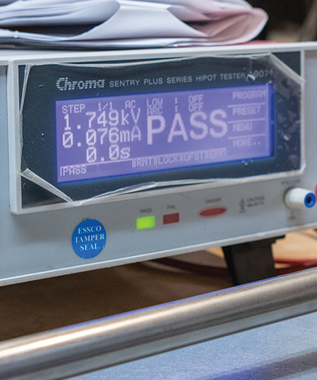
U.L. AND C-UL Recognized
No. E177353
Features
- The Backer Hotwatt Tubular Heater has built-in resistance to shock, vibration, corrosion and temperature extremes.
- The heater is swaged, reducing the diameter of the metal sheath and compacting the insulation. This insures rapid heat transfer and holds the coil in position for forming.
- Many formations are available.
- Long, trouble free service.
- Made in U.S.A.
Construction
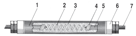
- Steel, stainless steel, copper, or Incoloy sheathed elements.
- Element wire situated in proximity to outside surface for maximum heat transfer and minimum internal temperature while preserving good dielectric qualities.
- Pure magnesium oxide compressed to an optimum density for best heat transfer and electrical insulation at elevated temperatures.
- Weld connection.
- Cold pin.
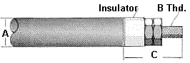
- Insulator.
- Standard post terminal.
Standard Sizes and Materials
The sheath materials available are stainless steel, steel, copper, and incoloy.
Standard diameters are: .260″, .315″, .375″, .440″and .475″.
Diameter tolerance is ± .010″.
Sheath Material | Max. Temp. Allowed on Sheath | Max. Length of Sheath | Max. Cold Lengths |
|---|---|---|---|
Steel | 750°F | 252″ | 96″ |
Copper | 350°F | 252″ | 96″ |
St. Steel | 1200°F | 324″ | 96″ |
Incoloy | 1600°F | 324″ | 96″ |
Sheath Materials and Watt Densities
Application | Approx. Operating Temp. | Rec. Sheath Material | Watts/sq.in. Of Element Surface |
|---|---|---|---|
Clamped to Surfaces | up to 300°F 500°F 800°F 1000°F 1200°F 1400°F | Steel Steel Incoloy Incoloy Incoloy Incoloy | 30 20 15 10 7 2.5 |
Still Air (Sheath Temp.) | 800°F 1000°F 1200°F 1400°F | Incoloy Incoloy Incoloy Incoloy | 7 11 14 30 |
Clamped into Machined Grooves | 500°F 800°F 900°F | Steel St. Steel Incoloy | 25 15 15 |
Formula for Determination of Unit Wattage
Unit Wattage = Diameter x 3.142 x Heated Length x Allowable watts/sq.in.
Electrical Tolerances and Limits
Sheath Diameter | .260″ | .315″ | .375″ | .440″ | .475″ |
|---|---|---|---|---|---|
Min. OHMS/in. | .15 | .05 | .05 | .05 | .05 |
Max. OHMS/in. | 80 | 50 | 50 | 50 | 50 |
Max. Voltage | 250 | 300 | 480 | 600 | 600 |
Max. Amperes | 20 | 30 | 40 | 40 | 40 |
Standard Length Tolerances
Sheath length | Length | Heated Length |
|---|---|---|
Up to 20″ | ± 1/16″ | ± 2% |
20″ to 100″ | ± 1/8″ | ± 2% |
100″ to 200″ | ± 1/4″ | ± 2% |
Cold Ends
When not specified, cold ends will be the minimum length as shown in table below. Longer cold lengths may be specified. Optional cold ends of unequal lengths are available.
Sheath length | Minimum Cold Ends |
|---|---|
Up to 20″ | 1″ |
20″ to 100″ | 1 1/2″ |
100″ to 200″ | 4″ |
Mount Fitting
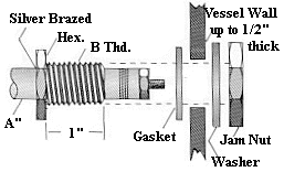
Fittings are available with light jam nuts (plated steel), plain washers (plated steel), and/or copper gaskets.
Brass bushings are used with copper and steel sheaths.Silver brazed stainless steel bushings are used with stainless steel and incoloy sheaths.Welded stainless steel bushings are available at additional cost.
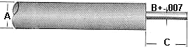
Catalog Number | Sheath Diameter A” | Thread Size B” |
|---|---|---|
EF-12 | .260″ | 1/2″-20 |
EF-13 | .315″ | 1/2″-20 |
EF-16 | .375″ | 5/8″-18 |
EF-17 | .440″ | 3/4″-16 |
EF-17 | .475″ | 3/4″-16 |
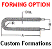
Forming
If you plan to do the bending required, observe the minimum bend limits in the table, and do not plan any bend within 1″ of a cold end junction. Annealing for bending must be specified. If Backer Hotwatt is to do the bending, submit a sketch showing clearly the form the bent unit is to take.
Minimum Bend Radius | |||||
|---|---|---|---|---|---|
Diameter | .260″ | .315″ | .375″ | .440″ | .475″ |
Formed By Factory | 1/4″ | 5/16″ | 3/8″ | 7/16″ | 7/16″ |
Formed By Customer | 3/4″ | 1″ | 1 1/4″ | 1 1/2″ | 1 1/2″ |
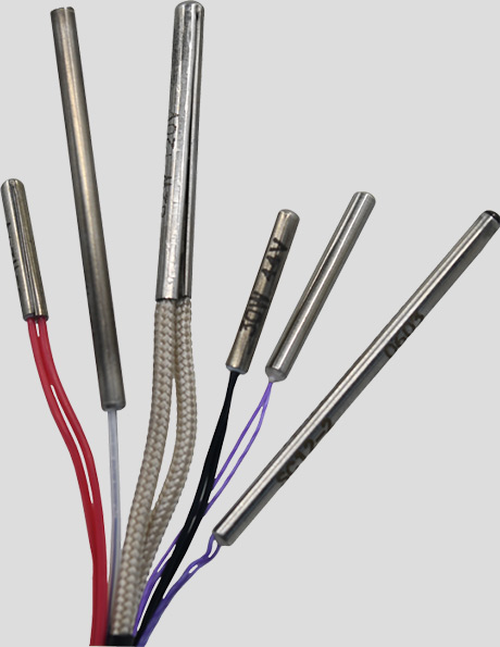
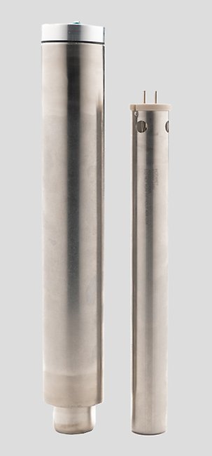
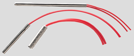
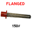
Optional Terminations
Post terminations will be supplied unless otherwise specified.
SF3S: Post
SF2A: Lead Wire
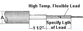
A” | B | C” | Max. Amps. | A” | Max. Amps. |
.260″ | 6-32 | 5/8″ | 20 | .260″ | 21 |
.315″ | 6-32 | 5/8″ | 20 | .315″ | 28 |
.375″ | 8-32 | 3/4″ | 30 | .375″ | 28 |
.375″ | 10-32 | 1″ | 40 | .440″ | 28 |
.440″ | 8-32 | 3/4″ | 30 | .475″ | 28 |
.440″ | 10-32 | 1″ | 40 | ||
.475″ | 10-32 | 1″ | 40 | ||
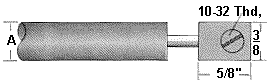
SF3P: Pin
SF23: Hermetic Seal
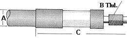
A” | B” | C” | Max. Amps. | A” | B | C” | Max. Amps. |
.260″ | .091″ | 5/8″ | 20 | .260″ | 8-32 | 1 11/16″ | 20 |
.315″ | .135″ | 5/8″ | 20 | .315″ | 10-32 | 1 7/8″ | 30 |
.375″ | .156″ | 3/4″ | 40 | .375″ | 10-32 | 1 7/8″ | 30 |
.440″ | .156″ | 3/4″ | 40 | .440″ | 1/4-28 | 2 1/8″ | 40 |
.475″ | .156″ | 3/4″ | 40 | .475″ | 1/4-28 | 2 1/8″ | 40 |
SF3T: Tab
SF11: Quick Connect
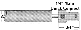
A” | Max. Amps. | A” | Max Amps. |
.260″ | 20 | .260″ | 20 |
.315″ | 30 | .315″ | 30 |
.375″ | 30 | .375″ | 30 |
.440″ | 30 | .440″ | 30 |
.475″ | 30 | .475″ | 30 |
Diameter: | .260: Incoloy | .315: Incoloy | .375: Incoloy | |||
|---|---|---|---|---|---|---|
Maximum Amperage: | 20 | 30 | 40 | |||
Sheath Length | Cat. No. | Max.Watts at 240V | Cat. No. | Max.Watts at 240V | Cat. No. | Max.Watts at 480V |
20″ | TA26-20 | 555 | TA31-20 | 675 | TA37-20 | 800 |
40″ | TA26-40 | 1210 | TA31-40 | 1465 | TA37-40 | 1745 |
60″ | TA26-60 | 1860 | TA31-60 | 2255 | TA37-60 | 2685 |
80″ | TA26-80 | 2515 | TA31-80 | 3050 | TA37-80 | 3630 |
100″ | TA26-100 | 3170 | TA31-100 | 3840 | TA37-100 | 4570 |
120″ | TA26-120 | 3825 | TA31-120 | 4630 | TA37-120 | 5515 |
140″ | TA26-140 | 4475 | TA31-140 | 5425 | TA37-140 | 6455 |
160″ | TA26-160 | 4640 | TA31-160 | 6215 | TA37-160 | 7395 |
180″ | TA26-180 | 4640 | TA31-180 | 7010 | TA37-180 | 8340 |
200″ | TA26-200 | 4640 | TA31-200 | 7005 | TA37-200 | 9285 |
220″ | TA26-220 | 4640 | TA31-220 | 7005 | TA37-220 | 10225 |
240″ | TA26-240 | 4640 | TA31-240 | 7005 | TA37-240 | 11170 |
Diameter: | .440: Incoloy | .475: Incoloy | .260: St. Steel | |||
|---|---|---|---|---|---|---|
Maximum Amperage: | 40 | 50 | 20 | |||
Sheath Length | Cat. No. | Max.Watts at 480V | Cat. No. | Max.Watts at 480V | Cat. No. | Max.Watts at 240V |
20″ | TA44-20 | 960 | TA47-20 | 1055 | TT26-20 | 420 |
40″ | TA44-40 | 2090 | TA47-40 | 2300 | TT26-40 | 910 |
60″ | TA44-60 | 3225 | TA47-60 | 3545 | TT26-60 | 1395 |
80″ | TA44-80 | 4355 | TA47-80 | 4790 | TT26-80 | 1885 |
100″ | TA44-100 | 5485 | TA47-100 | 6035 | TT26-100 | 2375 |
120″ | TA44-120 | 6615 | TA47-120 | 7280 | TT26-120 | 2865 |
140″ | TA44-140 | 7745 | TA47-140 | 8520 | TT26-140 | 3355 |
160″ | TA44-160 | 8880 | TA47-160 | 9765 | TT26-160 | 3845 |
180″ | TA44-180 | 10010 | TA47-180 | 11010 | TT26-180 | 4340 |
200″ | TA44-200 | 11140 | TA47-200 | 12255 | TT26-200 | 4705 |
220″ | TA44-220 | 12270 | TA47-220 | 13495 | TT26-220 | 4705 |
240″ | TA44-240 | 13400 | TA47-240 | 14740 | TT26-240 | 4705 |
Diameter: | .315: St. Steel | .375: St. Steel | .440: St. Steel | |||
|---|---|---|---|---|---|---|
Maximum Amperage: | 30 | 40 | 40 | |||
Sheath Length | Cat. No. | Max.Watts at 240V | Cat. No. | Max.Watts at 240V | Cat. No. | Max.Watts at 480V |
20″ | TT31-20 | 505 | TT37-20 | 600 | TT44-20 | 720 |
40″ | TT31-40 | 1095 | TT37-40 | 1305 | TT44-40 | 1570 |
60″ | TT31-60 | 1690 | TT37-60 | 2015 | TT44-60 | 2415 |
80″ | TT31-80 | 2285 | TT37-80 | 2720 | TT44-80 | 3265 |
100″ | TT31-100 | 2880 | TT37-100 | 3425 | TT44-100 | 4115 |
120″ | TT31-120 | 3475 | TT37-120 | 4135 | TT44-120 | 4960 |
140″ | TT31-140 | 4065 | TT37-140 | 4840 | TT44-140 | 5810 |
160″ | TT31-160 | 4660 | TT37-160 | 5550 | TT44-160 | 6660 |
180″ | TT31-180 | 5255 | TT37-180 | 6255 | TT44-180 | 7505 |
200″ | TT31-200 | 5850 | TT37-200 | 6965 | TT44-200 | 8355 |
220″ | TT31-220 | 6440 | TT37-220 | 7670 | TT44-220 | 9205 |
240″ | TT31-240 | 7035 | TT37-240 | 8375 | TT44-240 | 10050 |
Diameter: | .260: Steel | .315: Steel | .440: Steel | |||
|---|---|---|---|---|---|---|
Maximum Amperage: | 20 | 30 | 40 | |||
Sheath Length | Cat. No. | Max.Watts at 240V | Cat. No. | Max.Watts at 240V | Cat. No. | Max.Watts at 240V |
20″ | TS26-20 | 280 | TS31-20 | 335 | TS44-20 | 480 |
40″ | TS26-40 | 605 | TS31-40 | 730 | TS44-40 | 1045 |
60″ | TS26-60 | 930 | TS31-60 | 1130 | TS44-60 | 1610 |
80″ | TS26-80 | 1260 | TS31-80 | 1525 | TS44-80 | 2175 |
100″ | TS26-100 | 1585 | TS31-100 | 1920 | TS44-100 | 2745 |
120″ | TS26-120 | 1910 | TS31-120 | 2315 | TS44-120 | 3310 |
140″ | TS26-140 | 2240 | TS31-140 | 2710 | TS44-140 | 3875 |
160″ | TS26-160 | 2565 | TS31-160 | 3105 | TS44-160 | 4440 |
180″ | TS26-180 | 2890 | TS31-180 | 3505 | TS44-180 | 5005 |
200″ | TS26-200 | 3220 | TS31-200 | 3900 | TS44-200 | 5570 |
220″ | TS26-220 | 3545 | TS31-220 | 4295 | TS44-220 | 6135 |
240″ | TS26-240 | 3870 | TS31-240 | 4690 | TS44-240 | 6700 |
Diameter: | .315: Copper | .440: Copper | ||
|---|---|---|---|---|
Maximum Amperage: | 30 | 40 | ||
Sheath Length | Cat. No. | Max.Watts at 240V | Cat. No. | Max.Watts at 600V |
20″ | TC31-20 | 1345 | TC44-20 | 1925 |
40″ | TC31-40 | 2930 | TC44-40 | 4185 |
60″ | TC31-60 | 4515 | TC44-60 | 6445 |
80″ | TC31-80 | 6095 | TC44-80 | 8710 |
100″ | TC31-100 | 6890 | TC44-100 | 10970 |
120″ | TC31-120 | 6890 | TC44-120 | 13230 |
140″ | TC31-140 | 6890 | TC44-140 | 15495 |
160″ | TC31-160 | 6890 | TC44-160 | 17755 |
180″ | TC31-180 | 6890 | TC44-180 | 18885 |
200″ | TC31-200 | 6890 | TC44-200 | 18885 |
220″ | TC31-220 | 6890 | TC44-220 | 18885 |
240″ | TC31-240 | 6890 | TC44-240 | 18885 |
Wattage
Wattages as shown in the above tables are based on sheath material or voltage/amperage limitations. For allowable wattage for your application, refer to Sheath Material/Watt Density chart above.
How to Order
Specify: Catalog number, wattage, voltage, termination, and other optimal features. If forming is required, include a dimensional sketch and reference formation number, if applicable.
Example: TA3140/1000W/240V/SF3S