


MARKETS


TUBULAR & FINNED TUBULAR
PRODUCTS
- Backer Hotwatt
- / Our Products
- / Tubular and Finned Tubular
- / Tubular Heaters Flanged
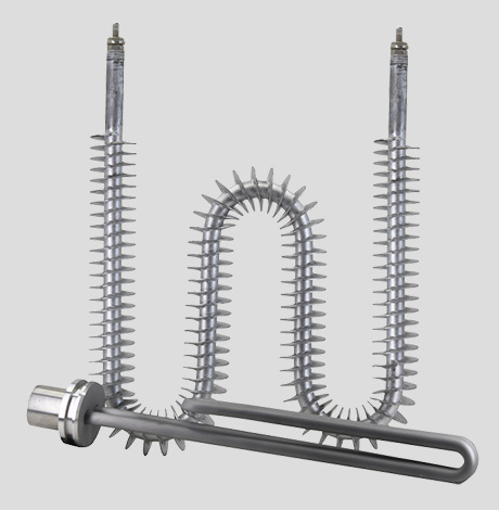
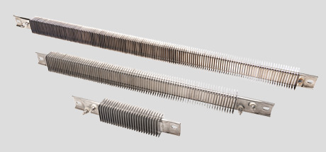
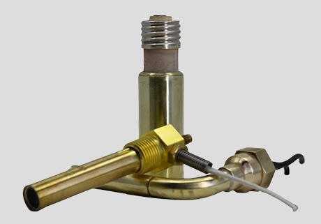
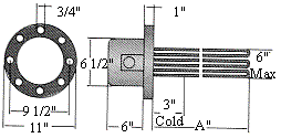
Tubular Heaters flanged
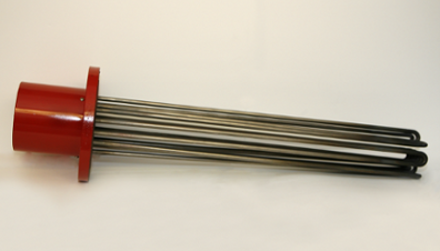


Description
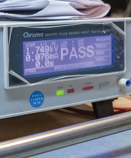
UL and C-UL Recognized – E177353
Features
- Ratings and sizes other than those listed are available.
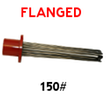
- 150# rating ANSI carbon steel flange.
- Steel, stainless steel, copper, or incoloy sheathed elements.
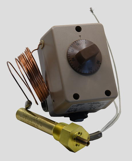
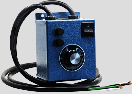
- Optional thermostat and well for temperature control.
- Element supports in multiple element units for proper element spacing as required.
- General purpose terminal housing with conduit openings. Optional terminal housing available for special applications.
- 240v and 480v, single and three phase which are factory wired to your requirements.
- Long, trouble free service
- Made in USA
Construction
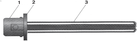
- Terminal housing, NEMA 1 general purpose, for electrical connections.
- Standard pipe flange.
- Tubular heating element.
Flanged Heater Selection Guide
High Viscosity Oil
Application | Solution or | Alkaline or | Sheath | Typical |
|---|---|---|---|---|
Water and Very Mild Solutions | Clean Water | pH6 to
pH8 Neutral | Copper | 45 |
Process Water or Very Mild Solutions | pH5 to pH9 2-3% | Incoloy | 45 | |
Mild Solutions | 5-6% | Incoloy | 45 | |
Demineralized or Deionized Water | — | Incoloy | 45 | |
Oil Heating* | Low Viscosity Oil | — | Steel | 23 |
Medium Viscosity
Oil | — | Steel | 15 | |
— | Steel | 6 | ||
Specialty Heaters | Small Tanks | — | ||
Process Water Demineralized Water Low Viscosity Oil | pH5-pH9 — — | Incoloy Incoloy Incoloy | 45 | |
Pipe Insert | — | Incoloy | 12 | |
Hot Tubs, Spa | Treated | Incoloy | 100 | |
Commercial Equipment | Clean Water Clean
Water | Incoloy Copper | 30 60 | |
Air, Gases, and Steam Heating | Low Temperature | — | Stainless Steel | 23 |
High Temperature | — | Incoloy | 23 |
*The following oil heaters are catalogued based on low viscosity oil. For medium and high viscosity oils, watt densities must be reduced in accordance with the above watt densities.
Installation
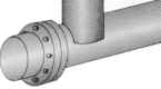
The heater is bolted onto a mating flange which is welded to a tank wall or a pipe. Terminal housings to enclose electrical connections are included.
Oil Tank Heater
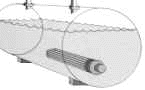
In-Line Fluid or Gas Heater
Steel Sheath: 150 lb Steel Flange
3″ Flange: Steel Sheath | ||
No. of Elements: 3 | ||
Watts/sq. in: 23 | ||
Application: Low Viscosity Oil |
Lgth. Inside | Cat. No. | Kilo- | Volts | Phase | |
|---|---|---|---|---|---|
18 1/16″ | BS3-18.06-J | 3.0 | 240 | 1 | |
18 1/16″ | BS3-18.06-J | 3.0 | 240 | 3 | |
25 3/16″ | BS3-25.18-J | 4.5 | 240 | 1 | |
25 3/16″ | BS3-25.18-J | 4.5 | 240 | 3 | |
33 1/16″ | BS3-33.06-J | 6.0 | 240 | 1 | |
33 1/16″ | BS3-33.06-J | 6.0 | 240 | 3 | |
40 9/16″ | BS3-40.56-J | 7.5 | 240 | 3 | |
48 1/16″ | BS3-48.06-J | 9.0 | 240 | 1 | |
48 1/16″ | BS3-48.06-J | 9.0 | 240 | 3 | |
5″ Flange: Steel Sheath | ||
No. of Elements: 6 | ||
Watts/sq. in: 23 | ||
Application: Low Viscosity Oil |
Lgth. Inside | Cat. No. | Kilo- | Volts | Phase | |
|---|---|---|---|---|---|
25 3/16″ | BS5-25.18-J | 9.0 | 240 | 3 | |
33 1/16″ | BS5-33.06-J | 12.0 | 240 | 3 | |
40 9/16″ | BS5-40.56-J | 15.0 | 240 | 3 | |
52 1/16″ | BS5-52.06-J | 20.0 | 240 | 3 | |
65 1/16″ | BS5-65.06-J | 25.0 | 240 | 3 | |
78 1/16″ | BS5-78.06-J | 30.0 | 240 | 3 | |

6″ Flange: Steel Sheath | ||
No. of Elements: 12 | ||
Watts/sq. in: 23 | ||
Application: Low Viscosity Oil |
Lgth. Inside | Cat. No. | Kilo- | Volts | Phase | |
|---|---|---|---|---|---|
25 1/8″ | BS6-25.12-J | 18.0 | 240 | 3 | |
33″ | BS6-33-J | 24.0 | 240 | 3 | |
40 1/2″ | BS6-40.5-J | 30.0 | 240 | 3 | |
48″ | BS6-48-J | 36.0 | 240 | 3 | |
8″ Flange: Steel Sheath | ||
No. of Elements: 18 | ||
Watts/sq. in: 23 | ||
Application: Low Viscosity Oil |
Lgth. Inside | Cat. No. | Kilo- | Volts | Phase | |
|---|---|---|---|---|---|
32 7/8″ | BS8-32.87-J | 30.0 | 240 | 3 | |
43 11/16″ | BS8-43.68-J | 40.0 | 240 | 3 | |
51 7/8″ | BS8-51.87-J | 50.0 | 240 | 3 | |
61 3/8″ | BS8-61.37-J | 60.0 | 240 | 3 | |
61 3/8″ | BS8-61.37-J | 60.0 | 480 | 3 | |
69 7/8″ | BS8-69.87-J | 70.0 | 240 | 3 | |
69 7/8″ | BS8-69.87-J | 70.0 | 480 | 3 | |
78 7/8″ | BS8-78.87-J | 80.0 | 240 | 3 | |
78 7/8″ | BS8-78.87-J | 80.0 | 480 | 3 | |
Stainless Steel Sheath: 150 Steel Flange

3″ Flange: Stainless Steel Sheath | ||
No. of Elements: 3 | ||
Watts/sq. in: 45 | ||
Application: Process Water and Very Mild Solution |
Lgth. Inside | Cat. No. | Kilo- | Volts | Phase | |
|---|---|---|---|---|---|
18 1/16″ | BT3-18.06-J | 6.0 | 240 | 1 | |
18 1/16″ | BT3-18.06-J | 6.0 | 240 | 3 | |
25 3/16″ | BT3-25.18-J | 9.0 | 240 | 1 | |
25 3/16″ | BT3-25.18-J | 9.0 | 240 | 3 | |
33 1/16″ | BT3-33.06-J | 12.0 | 240 | 1 | |
33 1/16″ | BT3-33.06-J | 12.0 | 240 | 3 | |
40 9/16″ | BT3-40.56-J | 15.0 | 240 | 1 | |
40 9/16″ | BT3-40.56-J | 15.0 | 240 | 3 | |
48 1/16″ | BT3-48.06-J | 18.0 | 240 | 1 | |
48 1/16″ | BT3-48.06-J | 18.0 | 240 | 3 | |

5″ Flange: Stainless Steel Sheath | ||
No. of Elements: 6 | ||
Watts/sq. in: 45 | ||
Application: Process Water and Very Mild Solution |
Lgth. Inside | Cat. No. | Kilo- | Volts | Phase | |
|---|---|---|---|---|---|
18 1/16″ | BT5-18.06-J | 12.0 | 240 | 3 | |
19 13/16″ | BT5-19.81-J | 15.0 | 240 | 3 | |
25 3/16″ | BT5-25.18-J | 18.0 | 240 | 3 | |
33 1/16″ | BT5-33.06-J | 24.0 | 240 | 3 | |
40 9/16″ | BT5-40.56-J | 30.0 | 240 | 3 | |
52 1/16″ | BT5-52.06-J | 40.0 | 240 | 3 | |
65 1/16″ | BT5-65.06-J | 50.0 | 240 | 3 | |
78 1/16″ | BT5-78.06-J | 60.0 | 240 | 3 | |

6″ Flange: Stainless Steel Sheath | ||
No. of Elements: 12 | ||
Watts/sq. in: 45 | ||
Application: Process Water and Very Mild Solution |
Lgth. Inside | Cat. No. | Kilo- | Volts | Phase | |
|---|---|---|---|---|---|
25 1/8″ | BT6-25.12-J | 36.0 | 240 | 3 | |
33″ | BT6-33-J | 48.0 | 240 | 3 | |
40 1/2″ | BT6-40.5-J | 60.0 | 240 | 3 | |
48″ | BT6-48-J | 72.0 | 240 | 3 | |
8″ Flange: Stainless Steel Sheath | ||
No. of Elements: 18 | ||
Watts/sq. in: 45 | ||
Application: Process Water and Very Mild Solution |
Lgth. Inside | Cat. No. | Kilo- | Volts | Phase | |
|---|---|---|---|---|---|
27 7/8″ | BT8-27.87-J | 50.0 | 240 | 3 | |
36 7/8″ | BT8-36.87-J | 75.0 | 240 | 3 | |
43 11/16″ | BT8-43.68-J | 100.0 | 240 | 3 | |
51 7/8″ | BT8-51.87-J | 120.0 | 240 | 3 | |
61 3/8″ | BT8-61.37-J | 150.0 | 240 | 3 | |
69 7/8″ | BT8-69.87-J | 175.0 | 240 | 3 | |
78 7/8″ | BT8-78.87-J | 200.0 | 240 | 3 | |
Copper Sheath: 150 lb Steel Flange

3″ Flange: Copper Sheath | ||
No. of Elements: 3 | ||
Watts/sq. in: 45 | ||
Application: Water |
Lgth. Inside | Cat. No. | Kilo- | Volts | Phase | |
|---|---|---|---|---|---|
18 1/16″ | BC3-18.06-J | 6.0 | 240 | 1 | |
18 1/16″ | BC3-18.06-J | 6.0 | 240 | 3 | |
25 3/16″ | BC3-25.18-J | 9.0 | 240 | 1 | |
25 3/16″ | BC3-25.18-J | 9.0 | 240 | 3 | |
33 1/16″ | BC3-33.06-J | 12.0 | 240 | 1 | |
33 1/16″ | BC3-33.06-J | 12.0 | 240 | 3 | |
40 9/16″ | BC3-40.56-J | 15.0 | 240 | 1 | |
40 9/16″ | BC3-40.56-J | 15.0 | 240 | 3 | |
48 1/16″ | BC3-48.06-J | 18.0 | 240 | 1 | |
48 1/16″ | BC3-48.06-J | 18.0 | 240 | 3 | |

5″ Flange: Copper Sheath | ||
No. of Elements: 6 | ||
Watts/sq. in: 45 | ||
Application: Water |
Lgth. Inside | Cat. No. | Kilo- | Volts | Phase | |
|---|---|---|---|---|---|
18 1/16″ | BC5-18.06-J | 12.0 | 240 | 3 | |
19 13/16″ | BC5-19.81-J | 15.0 | 240 | 3 | |
25 3/16″ | BC5-25.18-J | 18.0 | 240 | 3 | |
33 1/16″ | BC5-33.06-J | 24.0 | 240 | 3 | |
40 9/16″ | BC5-40.56-J | 30.0 | 240 | 3 | |
52 1/16″ | BC5-52.06-J | 40.0 | 240 | 3 | |
65 1/16″ | BC5-65.06-J | 50.0 | 480 | 3 | |
78 1/16″ | BC5-78.06-J | 60.0 | 480 | 3 | |

6″ Flange: Copper Sheath | ||
No. of Elements: 12 | ||
Watts/sq. in: 45 | ||
Application: Water |
Lgth. Inside | Cat. No. | Kilo- | Volts | Phase | |
|---|---|---|---|---|---|
25 1/8″ | BC6-25.12-J | 36.0 | 240 | 3 | |
33″ | BC6-33-J | 48.0 | 240 | 3 | |
40 1/2″ | BC6-40.5-J | 60.0 | 240 | 3 | |
48″ | BC6-48-J | 72.0 | 240 | 3 | |

8″ Flange: Copper Sheath | ||
No. of Elements: 18 | ||
Watts/sq. in: 45 | ||
Application: Water |
Lgth. Inside | Cat. No. | Kilo- | Volts | Phase | |
|---|---|---|---|---|---|
27 7/8″ | BC8-27.87-J | 50.0 | 240 | 3 | |
36 7/8″ | BC8-36.87-J | 75.0 | 240 | 3 | |
43 11/16″ | BC8-43.68-J | 100.0 | 240 | 3 | |
51 7/8″ | BC8-51.87-J | 120.0 | 240 | 3 | |
61 3/8″ | BC8-61.37-J | 150.0 | 240 | 3 | |
69 7/8″ | BC8-69.87-J | 175.0 | 240 | 3 | |
78 7/8″ | BC8-78.87-J | 200.0 | 240 | 3 | |
Incoloy Sheath: 150 lb Steel Flange

3″ Flange: Incoloy Sheath | ||
No. of Elements: 3 | ||
Watts/sq. in: 45 | ||
Application: Mild Solution |
Lgth. Inside | Cat. No. | Kilo- | Volts | Phase | |
|---|---|---|---|---|---|
18 1/16″ | BA3-18.06-J | 6.0 | 240 | 1 | |
18 1/16″ | BA3-18.06-J | 6.0 | 240 | 3 | |
25 3/16″ | BA3-25.18-J | 9.0 | 240 | 1 | |
25 3/16″ | BA3-25.18-J | 9.0 | 240 | 3 | |
33 1/16″ | BA3-33.06-J | 12.0 | 240 | 1 | |
33 1/16″ | BA3-33.06-J | 12.0 | 240 | 3 | |
40 9/16″ | BA3-40.56-J | 15.0 | 240 | 1 | |
40 9/16″ | BA3-40.56-J | 15.0 | 240 | 3 | |
48 1/16″ | BA3-48.06-J | 18.0 | 240 | 1 | |
48 1/16″ | BA3-48.06-J | 18.0 | 240 | 3 | |

5″ Flange: Incoloy Sheath | ||
No. of Elements: 6 | ||
Watts/sq. in: 45 | ||
Application: Mild Solution |
Lgth. Inside | Cat. No. | Kilo- | Volts | Phase | |
|---|---|---|---|---|---|
18 1/16″ | BA5-18.06-J | 12.0 | 240 | 3 | |
19 13/16″ | BA5-19.81-J | 15.0 | 240 | 3 | |
25 3/16″ | BA5-25.18-J | 18.0 | 240 | 3 | |
33 1/16″ | BA5-33.06-J | 24.0 | 240 | 3 | |
40 9/16″ | BA5-40.56-J | 30.0 | 240 | 3 | |
52 1/16″ | BA5-52.06-J | 40.0 | 240 | 3 | |
65 1/16″ | BA5-65.06-J | 50.0 | 240 | 3 | |
78 1/16″ | BA5-78.06-J | 60.0 | 240 | 3 | |
6″ Flange: Incoloy Sheath | ||
No. of Elements:12 | ||
Watts/sq. in: 45 | ||
Application: Mild Solution |
Lgth. Inside | Cat. No. | Kilo- | Volts | Phase | |
|---|---|---|---|---|---|
25 1/8″ | BA6-25.12-J | 36.0 | 240 | 3 | |
33″ | BA6-33-J | 48.0 | 240 | 3 | |
40 1/2″ | BA6-40.5-J | 60.0 | 240 | 3 | |
48″ | BA6-48-J | 72.0 | 240 | 3 | |

8″ Flange: Incoloy Sheath | ||
No. of Elements: 18 | ||
Watts/sq. in: 45 | ||
Application: Mild Solution |
Lgth. Inside | Cat. No. | Kilo- | Volts | Phase | |
|---|---|---|---|---|---|
27 7/8″ | BA8-27.87-J | 50.0 | 240 | 3 | |
36 7/8″ | BA8-36.87-J | 75.0 | 240 | 3 | |
43 11/16″ | BA8-43.68-J | 100.0 | 240 | 3 | |
51 7/8″ | BA8-51.87-J | 120.0 | 240 | 3 | |
61 3/8″ | BA8-61.37-J | 150.0 | 240 | 3 | |
69 7/8″ | BA8-69.87-J | 175.0 | 240 | 3 | |
78 7/8″ | BA8-78.87-J | 200.0 | 240 | 3 | |
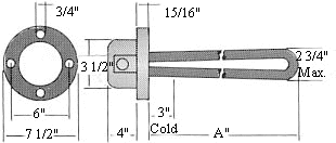
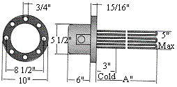
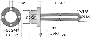
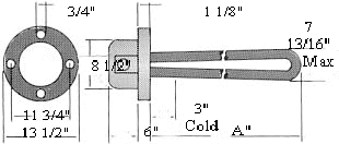
Dimensions

Available on: 3″, 5″, 6″, 8″, flanged. Enclosure sizes vary with element sizes.
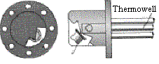
XS-55: Thermostat control. Integral bulb and capillary control with thermowell. Two temperature ranges available. Specify XS-55 (0° – 100° F) or XS-55 (60° – 250° F).
Available on: 3″, 5″, 6″, 8″, flanged. Enclosure sizes vary with element sizes.
How To Order
Specify: Catalog number, wattage, voltage, and special features, if any. Other sizes are available. Consult factory.
Example: BS3-18.06-J/1000W120V